- ABOUT LANTECH
- PRODUCTS
Hardened Ethernet Connections
- Introducing Flagship OS5 Switches
- Introducing Layer3 OS3/OS4 Switches
- Introducing Vehicle OS2 PRO Switches
- EN50155 10G Uplinks Managed Ethernet Switches
- EN50155 2.5G Uplinks Managed Ethernet Switches
- EN50155 Giga Uplinks Managed Ethernet Switches
- EN50155 Unmanaged Ethernet Switches
- EN50155 IEC 61375 Ethernet Switches
- EN50155 Rackmount Ethernet Switches
- Tram/Vehicle Switches and Routers (E-Mark / ITxPT)
- Industrial Managed Switches
- Industrial 10G Switches
- Industrial 2.5G Switches
- Industrial Rackmount Switches
- Industrial PoE Solutions
- Industrial Unmanaged Switches
- Industrial Converter Series
Hardened Routers
Software / Accessories

Naming Rule
- SOLUTIONS
- LEARNING CENTER
- CASE STUDY
- SUPPORT
- NEWS / EVENTS
- CONTACT US
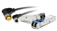
10G Copper SFP+ Transceiver, 30M
- Distance: 30M
- Standard Operating Temperature: 0°C ~ 70°C
- Wide Operating Temperature: -40°C ~ 85°C
- 1G/ 2.5G/ 5G/ 10GBase-T Application
OVERVIEW
Lantech SFP-10GB-T Small Form Factor Pluggable SFP+ Copper transceivers are compliant with the current SFP+ Multi-Source Agreement (MSA) Specification. The high performance designed is integrated full duplex data link at 10Gbps over four pair Category 6a/7 cable up to 30m links. It is specifically designed for high speed communication links that require 10 Gigabit Ethernet over copper cable.
FEATURES
- Compliant with IEEE 802.3az, 802.3ab and 802.3 standard
- Compliant with SFP+ MSA (SFF-8431, SFF-8432)
- Support 10GBase-T/ 5GBase-T/ 2.5GBase-T/ 1000Base-T
- Hot Pluggable
- Auto-negotiates with other 10GBase-T PHYs
- Auto-detect MDI/MDI-X
- Support RX_LOS function
- I2C 2-wire interface for serial ID and PHY register access
- RJ-45 connector
- Single +3.3V power supply
- 10G link length up to 30m with Cat.6a/7, 2.5G/5G link length up to 50m with Cat.5E, 1G link length up to 100m with Cat.5E
- RoHS Compliant
SPECIFICATIONS
Absolute Maximum Ratings
Parameter |
Symbol |
Min. |
Max. |
Unit |
Note |
Storage Temperature |
TsT |
-40 |
+85 |
°C |
|
Supply Voltage |
VccT, VccR |
-0.5 |
+4.0 |
V |
|
Storage Relative Humidity |
RH |
5 |
95 |
% |
|
Recommended Operating Conditions
Parameter |
Symbol |
Min. |
Typ. |
Max. |
Unit |
Note |
Case Operating Temperature |
ToP |
0 |
- |
+70 |
°C |
|
Case Operating Temperature (-E model) |
ToP |
-40 |
- |
+85 |
°C |
|
Supply Voltage |
Vcc |
+3.13 |
+3.3 |
+3.47 |
V |
|
Supply Current |
Icc |
|
|
880 |
mA |
|
Power Consumption @30M |
PCW |
|
|
2.9 |
W |
|
General Specifications
Vcc= 3.15V to 3.46V, Top = 0 C to 70 C
Parameter |
Symbol |
Min. |
Typ. |
Max. |
Unit |
Note |
Data Rate |
DR |
1 |
10.3125 |
|
GB/sec |
|
Bit Error Rate |
BER |
|
|
10-12 |
|
|
High-Speed Electrical Interface, Host to SFP+
Vcc= 3.13V to 3.47V, Top = 0 C to 70 C
Parameters |
Symbol |
Min. |
Typ. |
Max. |
Unit |
Note |
||
TD+, TD- Input Voltage Swing |
VIN+ / VIN- |
250 |
|
1200 |
mV |
1 |
||
RD+, RD- Output Voltage Swing |
Vout+ / Vout- |
350 |
|
800 |
mV |
1 |
||
Rise Time (Receiver) |
Tr |
|
175 |
|
ps |
2 |
||
Fall Time (Receiver) |
Tf |
|
175 |
|
ps |
2 |
||
Tx Input Impedeance |
Zin |
|
50 |
|
Ohm |
1 |
||
Rx Output Impedeance |
Zout |
|
50 |
|
Ohm |
1 |
||
|
Note1: Single ended Note2: 20% to 80% value |
||||||||
High-Speed Electrical Interface, Cable to SFP+
Vcc= 3.13V to 3.47V, Top = 0 C to 70 C
Parameters |
Symbol |
Min. |
Typ. |
Max. |
Unit |
Note |
||
TX Output Impedance |
Zout.TX |
|
100 |
|
Ohm |
1 |
||
RX Output Impedance |
Zin.RX |
|
100 |
|
Ohm |
1 |
||
|
Note1: Differential for frequencies ranging from 125MHz to 10.3125GHz |
||||||||
Pin Assignment
|
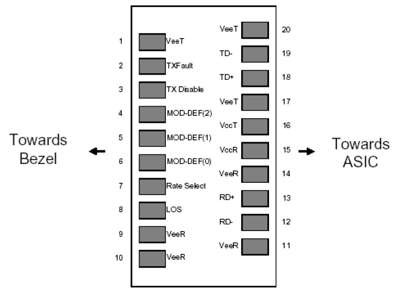
Pin Description
Pin |
Name |
Function / Description |
1 |
VeeT |
Transmitter Ground |
2 |
TX_Fault |
Transmitter Fault Indication (1) |
3 |
TX_Disable |
Transmitter Disable – Turns off transmitter laser output (2) |
4 |
SDA |
2-wire Serial Interface Data Line (SDA: Serial Data Signal) (3) |
5 |
SCL |
2-wire Serial Interface Clock (SCL: Serial Clock Signal) (3) |
6 |
Mod_ABS |
Module Absent, connected to VeeT or VeeR in the module (3) |
7 |
RS0 |
Rate Select 0, optionally controls SFP+ module receiver (5) |
8 |
Rx_LOS |
Receiver Loss of Signal Indication (4) |
9 |
RS1 |
Rate Select 1, optionally controls SFP+ module transmitter (5) |
10 |
VeeR |
Receiver Ground |
11 |
VeeR |
Receiver Ground |
12 |
RD- |
Receiver Inverted Data output, Differential LVPECL, AC coupled |
13 |
RD+ |
Receiver Non-Inverted Data output, Differential LVPECL, AC coupled |
14 |
VeeR |
Receiver Ground |
15 |
VccR |
Receiver 3.3V Power Supply |
16 |
VccT |
Transmitter 3.3V Power Supply |
17 |
VeeT |
Transmitter Ground |
18 |
TD+ |
Transmitter Non-Inverted Data Input, Differential LVPECL, AC coupled |
19 |
TD- |
Transmitter Inverted Data Input, Differential LVPECL, AC coupled |
20 |
VeeT |
Transmitter Ground |
Note1: TX Fault is not used and is always tied to ground through a 100 ohm resistor. |
||
DIMENSION
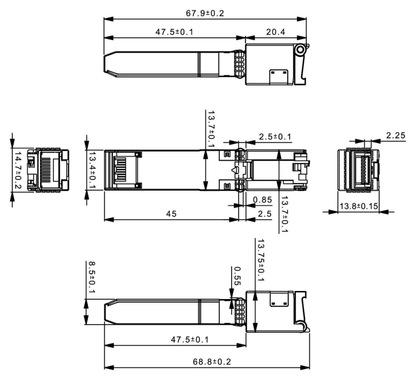 *All dimensions are ±0.2mm unless otherwise specified
ORDERING INFORMATION
Part Number |
Speed mode |
Link |
Temp. |
8330-206-V1 |
10GBase-T @Cat.6a/7 cable |
30 meters |
0~70°C |
5GBase-T/2.5GBase-T @Cat.5E cable |
50 meters |
||
1000Base-T @Cat.5E cable |
100 meters |
||
8330-206E-V1 |
10GBase-T @Cat.6a/7 cable |
30 meters |
-40~85°C |
5GBase-T/2.5GBase-T @Cat.5E cable |
50 meters |
||
1000Base-T @Cat.5E cable |
100 meters |